AM36 Last Group - Croc // 2007
Animal Behaviour Robot
The objective of the AM36 2007 course was to build an animal-like robot, using Lego Mindstorms NXT, for the RobotsAtPlay Festival 2007. Specific requirements included: Not using wheels for propulsion, some form of interactivity available, and ready in two weeks.
Designing the Robot
The following drawings were made for the initial design of the robot. The head and body were implemented in the basic style sketched here, while several changes were made to the design of the legs. Additionally, some of the planned sensors were not used, and the activities linked to those sensors not implemented.
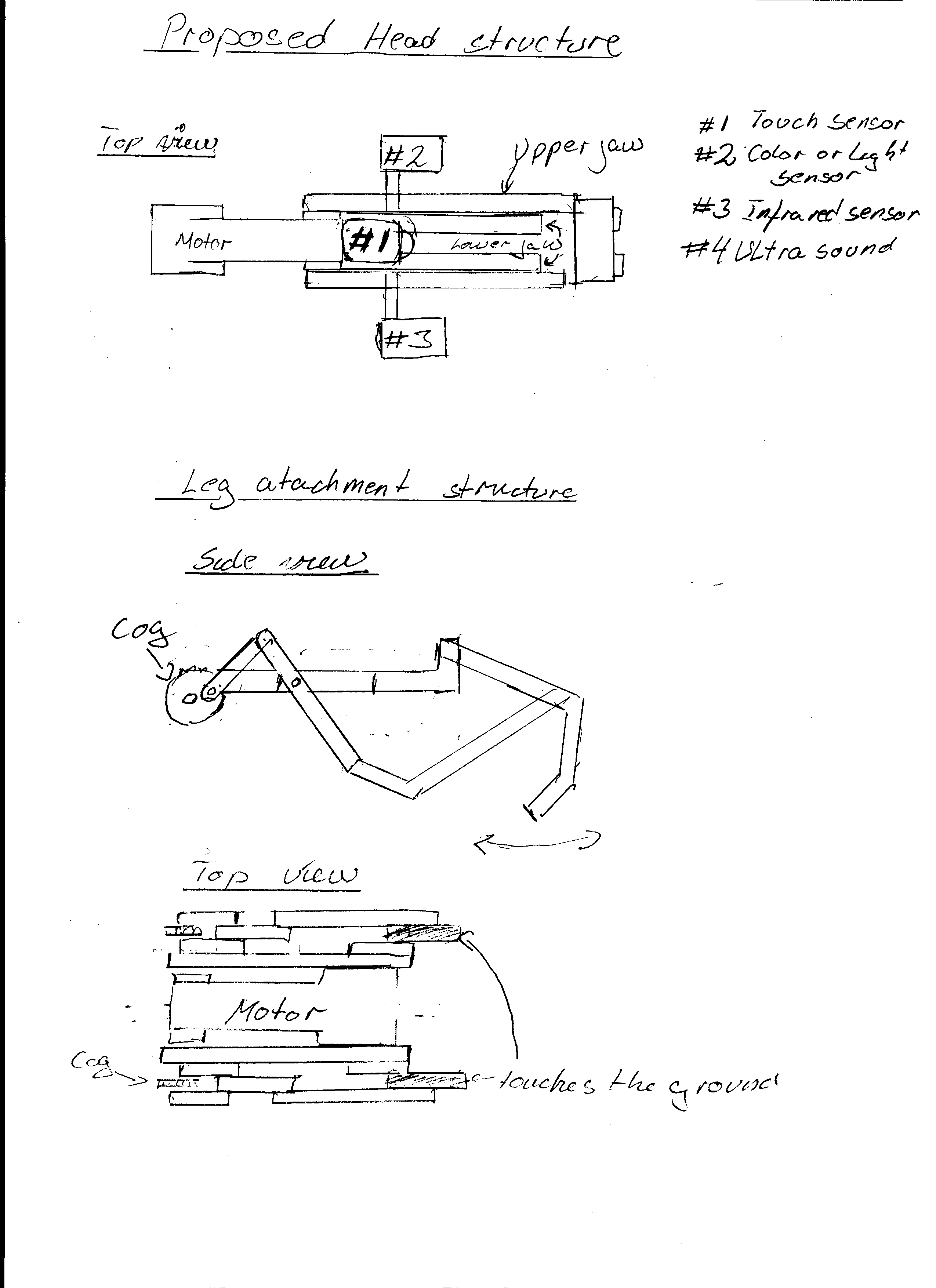
and a first draft of possible design for legs.
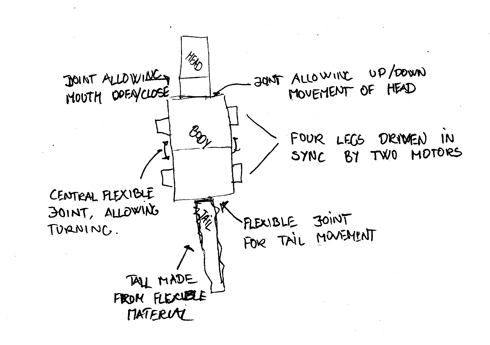
Approximate proportions, and sensor placement.
The following sections are the design document containing the original plans for interaction, software, use of sensors etc.
Concept
The Lego Crocodile is an interactive Lego model, resembling in outlook and behaviour a real crocodile. The model is capable of moving around, either because of activity in its proximity, as well as by its own will.
The model will in general remain passive, seeking to obtain a position in the sun, as other animals in the reptile family. Occasionally it will become active, either seeking a better position in the sun, or scavenging for food in its vicinity. The model can also be activated by other animals or humans entering its proximity. Depending on a number of things, including the interval since last eating, the crocodile will attempt to either engage the disturbance, or move to another position to resume sun bathing. Interactivity To make the robot interactive, the robot processes sensory input simulating sound, sight and touch. The robot will also have additional behaviour patterns, which are driven by a schedule. Finally, a remote controller, using Bluetooth, can activate several functions of the robot.
Activity patterns
The robot will actively try to place it self in a lighted area, seeking sunlight as other animals in the reptile family. It will stay in the light for a period of time, unless disturbed, an occasionally seek out a better spot. The robot can be "stirred" by entering into its field of vision, and will then react according to several variables. Either moving towards the object in its vision, or trying to back away and finding a new place to rest. The robot will send out sounds, warning intruders of its mood. As well as vision, the robot will use hearing to react to objects coming close to it. If stirred by its hearing, the robot will try to move around, seeking to get the disturbance into its field of vision. The robot will seek out food thrown to it, if it's hungry, and try to consume the food. Sensory input and output To simulate the behaviour of a real crocodile, the robot will utilise a number of both sensors and motors. The sensors are primarily placed in the head area, to simulate real sensory inputs, while the motors are placed throughout the robots body, where necessary.
Sensors
To create the correct behaviour and means of interaction, several sensors are used. The table below shows some of the sensors envisioned to be used in the robot, and their planned placement.
| Sensor type | Sensor placement | Sensor use |
| Light | Head | Finding sunlight |
| Ultra sound | Head | Distance measurement |
| Sound | Head | Waking from inactivity |
| Infrared | Head | Tracking items |
| Touch | Mouth | Discovering food (in mouth) |
The light sensor is used for finding a suitable place for the robot to "sleep". Using the light sensor the robot will scan the surroundings, and select a heading towards the brightest direction. The sensor is placed on in the head of the model, pointing forwards.
The ultra sound sensor is also placed in the head of the robot, and pointing forwards. The sensor is used for measuring distances to objects in front of the robot. The robot will use the sensor both for avoiding obstacles coming to close, and for seeking out objects when in "hunt mode".
The sound sensor is placed in the head area, and is used for making the robot react to sounds near its resting place. The robot will "wake" and try to turn towards the sound source. Optimally the robot will use more than one sensor to obtain sound source position more accurately.
The infrared sensor will be used for locating objects thrown to the robot. This for example includes feeding the robot, where the food contains an infrared emitter.
The touch sensor is placed internally in the robots mouth, and will make the robot react to food.
Interactive control
Apart from the sensory input processed by the robot, when working in "autonomous" mode, the robot will also accept input from a remote control, using Bluetooth. The remote should present a graphical and user-friendly interface, from which all of the robots behaviour patterns to be activated. Additionally the robots motor functions, like the mouth or the tail, can be activated and observed.
Sound
Apart from the physical movement of the robot, and its individual parts, the robot will also emit sound as part of its behaviour. The robot will emit crocodile-like sounds, reacting to its surroundings and according to its current mode (seeking food, sunbathing etc.).
Movement and physical behaviour
The robot will be moving around using four legs, and will have several flexible joints on its body. The head will be movable (up and down) and feature a mouth that can open and close. The robot will have a central flexible joint, driven by a motor, placed on the middle body to enhance directional control of the robot, as well as making the movement of the robot more natural. The tail will feature a joint, also driven by a motor, to make the tail swish in a realistic manner.
Head Development
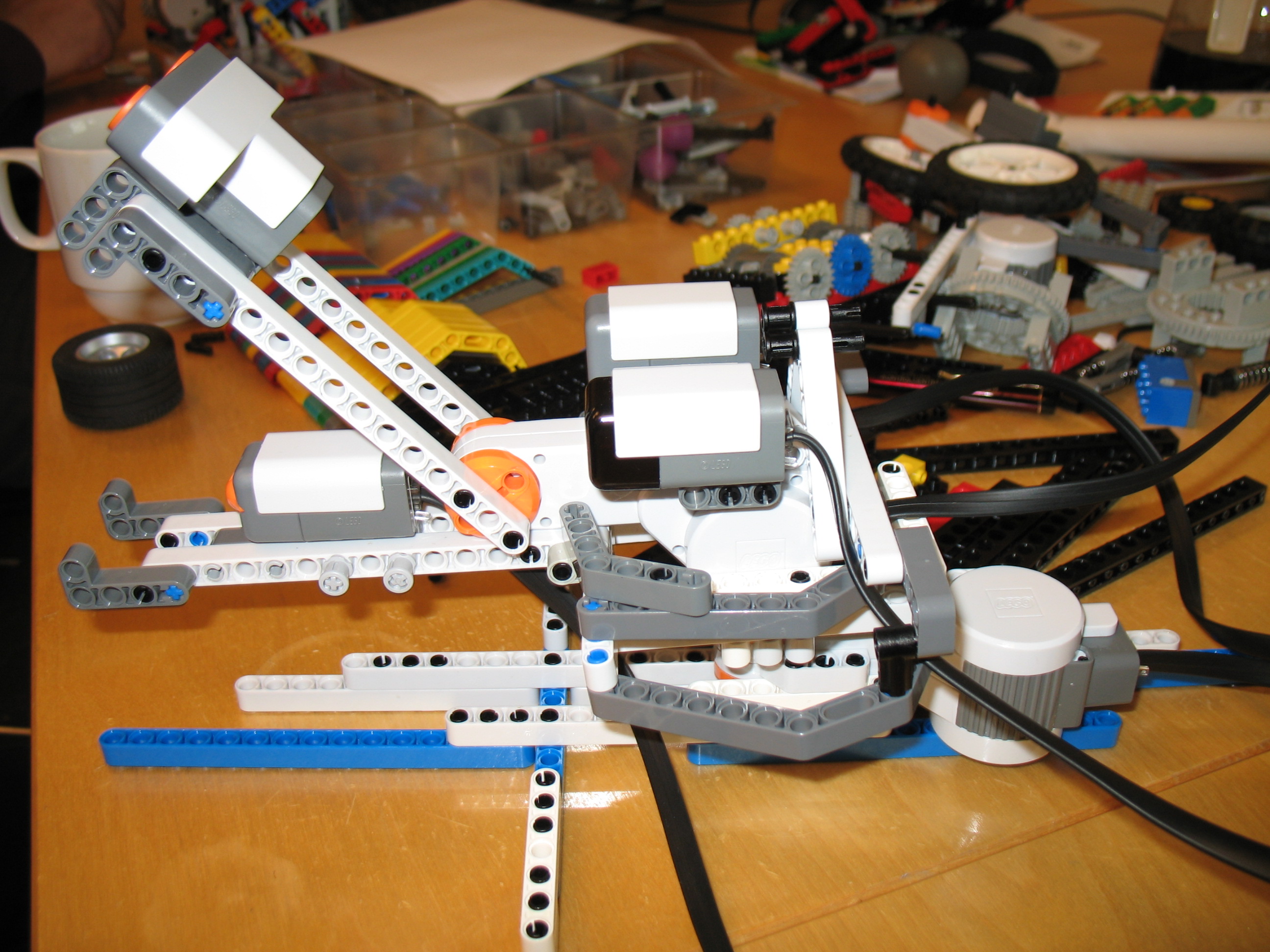
The head of the robot was developed based on the design developed early in the project. One motor was placed as the central part of the head, with the "jaws" protruding from the motor. By placing the sensors on the motor, we were able to give the impression of a real crocodile head. The following pictures show the head disconnected from the body.
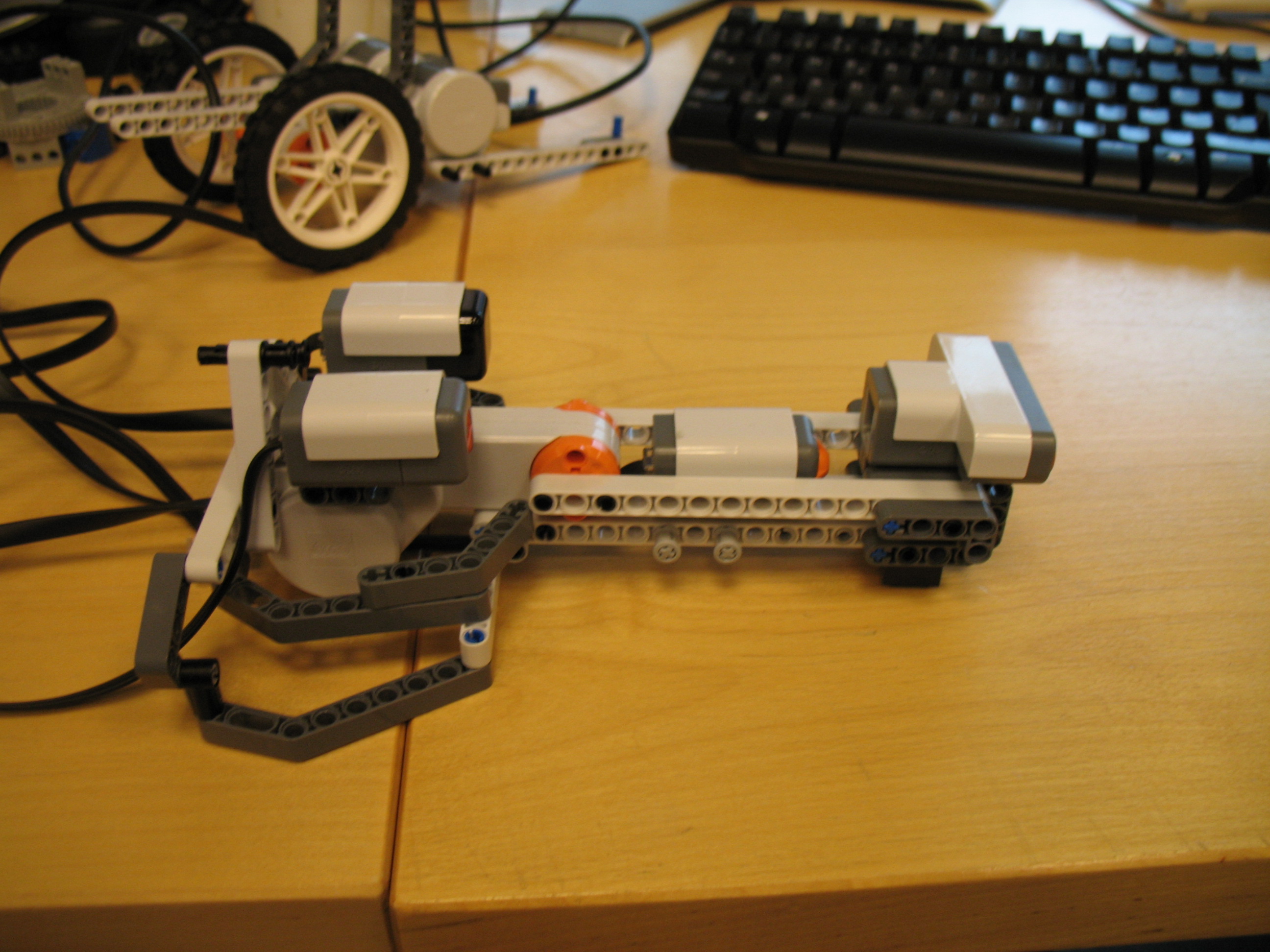
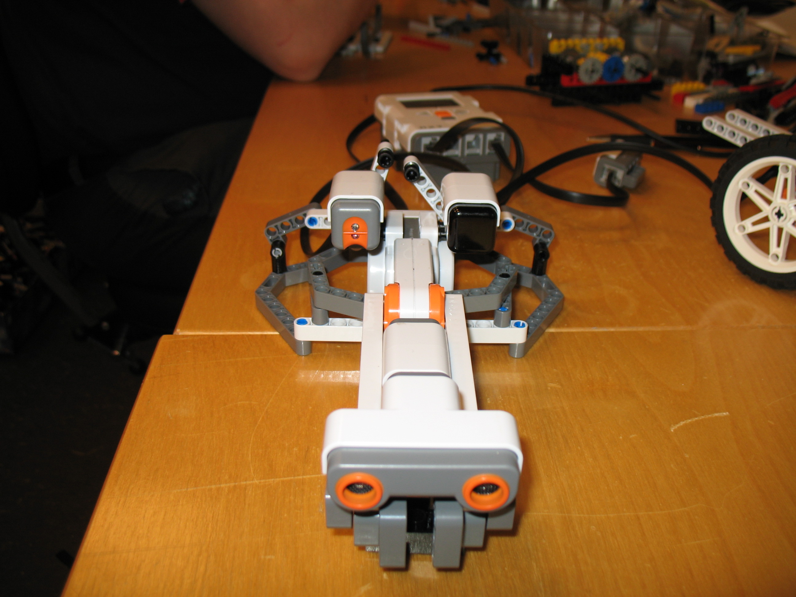
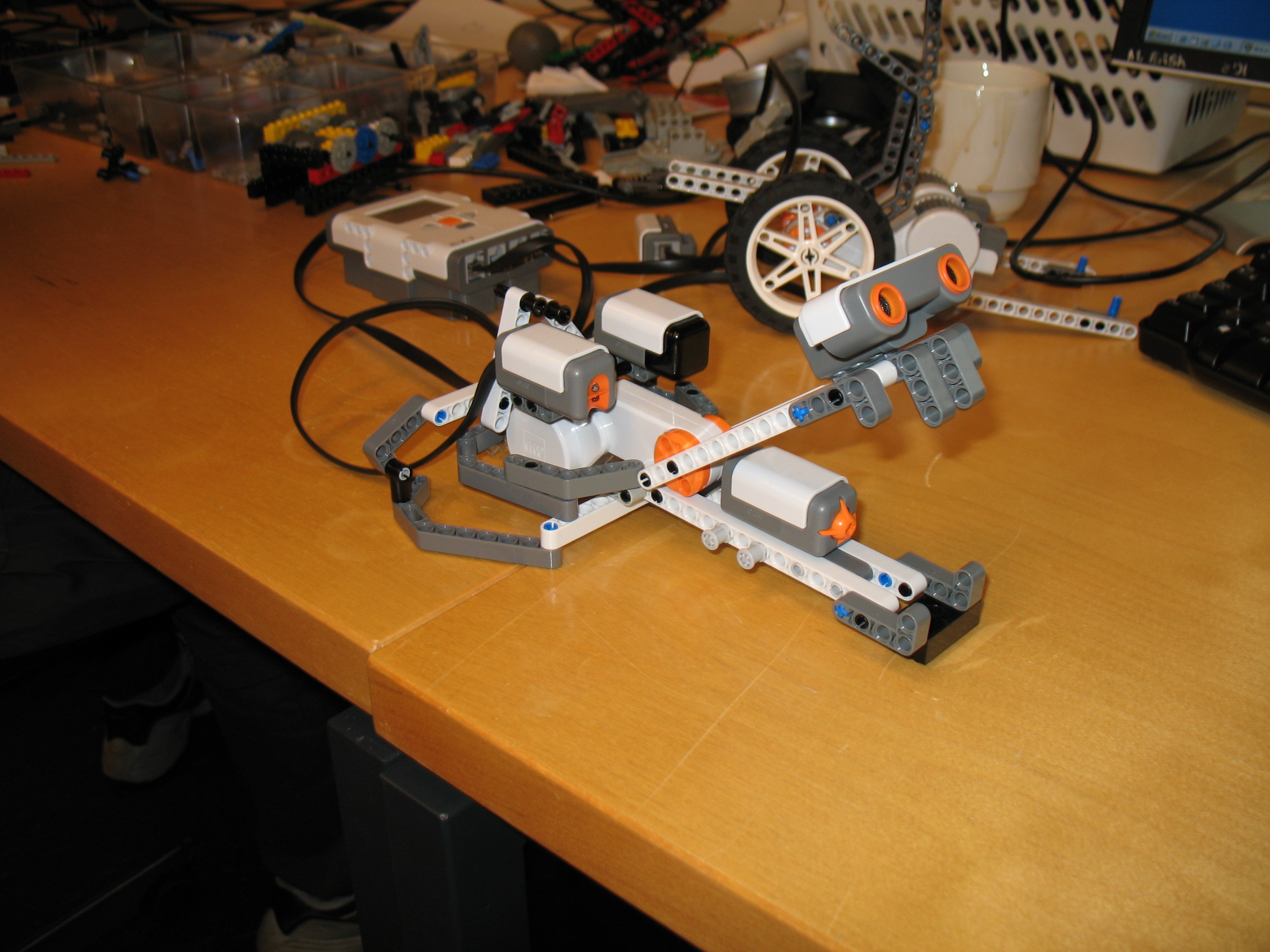
Finally the head was mounted on a vertical motor, enabling the robot to turn the head, relative to the direction of the body. The image below shows the head mounted on the motor, and the head placed on a test-platform
The video below shows a early test of the head's movement.
Torso Development
Skeleton Structure
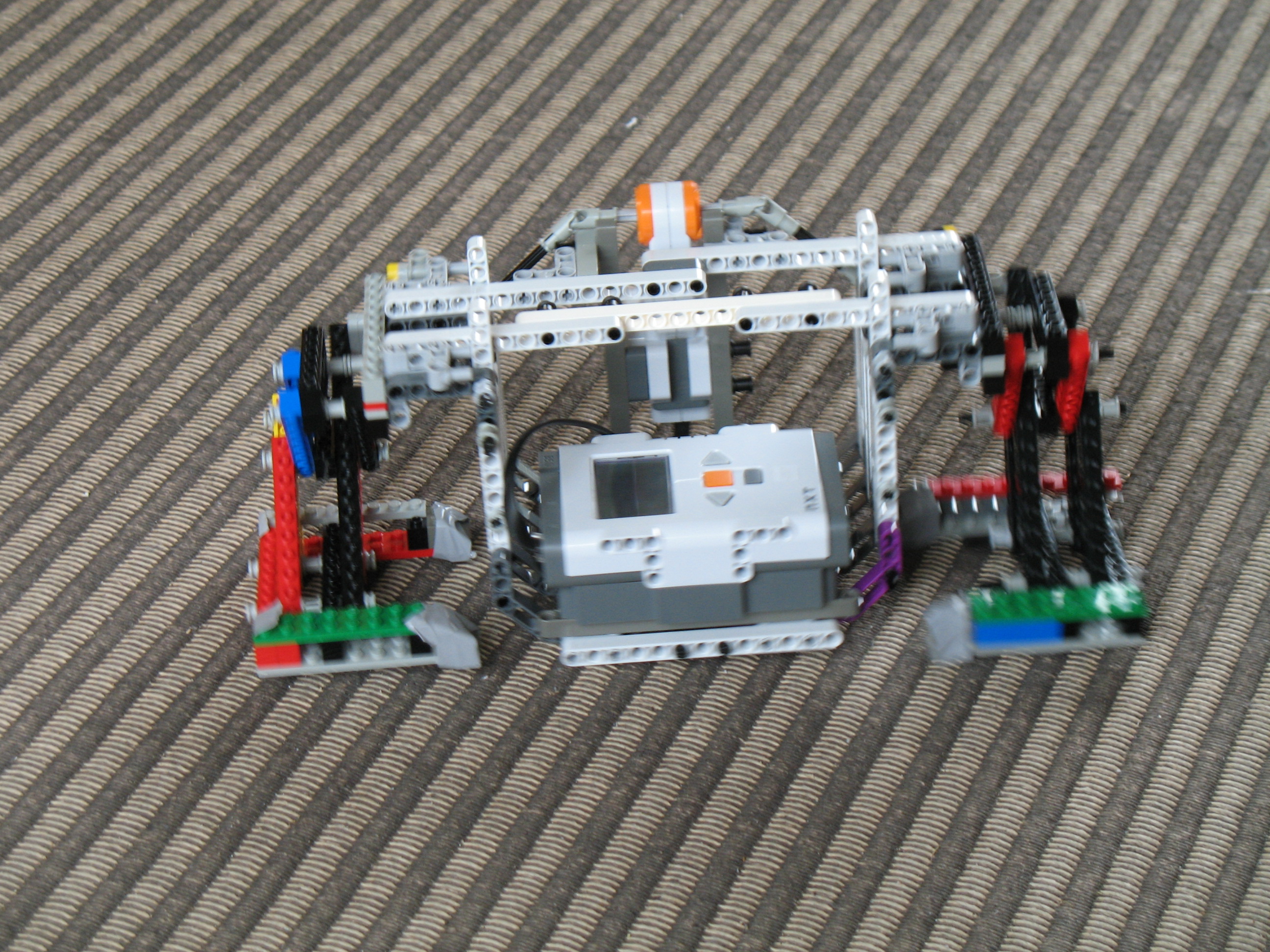
The torso of the robot was developed in two parts, the front and the the tail part. The pictures below show some early shots of the tail part, being build. In this version the NXT block is placed deep in the body of the robot to create a better balance when walking. In later versions the NXT is placed on top of the torso, to facilitate battery change in a convenient way. Additionally the space in the torso was later taken up by the motors for the head and the central joint.
The legs were a modified version of the legs from a bipedal walker from a earlier project. The rotational movement is converted to a walking motion by the construction of the legs, and not by gearing. The fact that the construction utilised a direct power transfer between motor and legs, meant that if the legs got caught in obstacles, the universal joints that connect the motor and leg could break under the tension. This happend several times during testing and demonstation, also when no obstacles were involved. Due to time constraints we only made minimal changes to the construction, in order to minimise the strain on the joints.
The legs on each torso is driven by one motor, these are both connected to the same NXT in order to drive both sets of legs in synchronisation. Since the legs are driven in pairs (front and tail) the turning of the robot is done by a third motor controlling the angle between the two torsoes
To maintain the balance of the robot when walking, the two parts of the robot, rests partly on the floor. By synchronising the legs, so that front left and tail right legs, and visa verse, is on the ground at the same time, and controlling the central joint, a minimum contact between the floor and the torsoes are created when moving. To further reduce the friction of the torsos against the floor, the robots is equipped with tiny wheels on the front of both parts. The image below show the wheels on the front torso. Other solutions were tried, but all resulted in too much friction on the surface that we had to walk on.
Because the torsoes were an integral part of the walking process, they were made as sturdy as possible. This was accomplished by creating a construction inspired by a real ribcage. This unfortunately meant that end result was a quite heavy construction. Because of that, an additional wheel was added at the centre of the robot, with the added bonus of improving the turning ability. An extra wheel at the rear, mainly to prevent the tail from dragging and getting caught in, was also added.
The Central Joint
The images below shows the two parts of the torso, in a later version, connected by a flexible joint, controlled by a motor
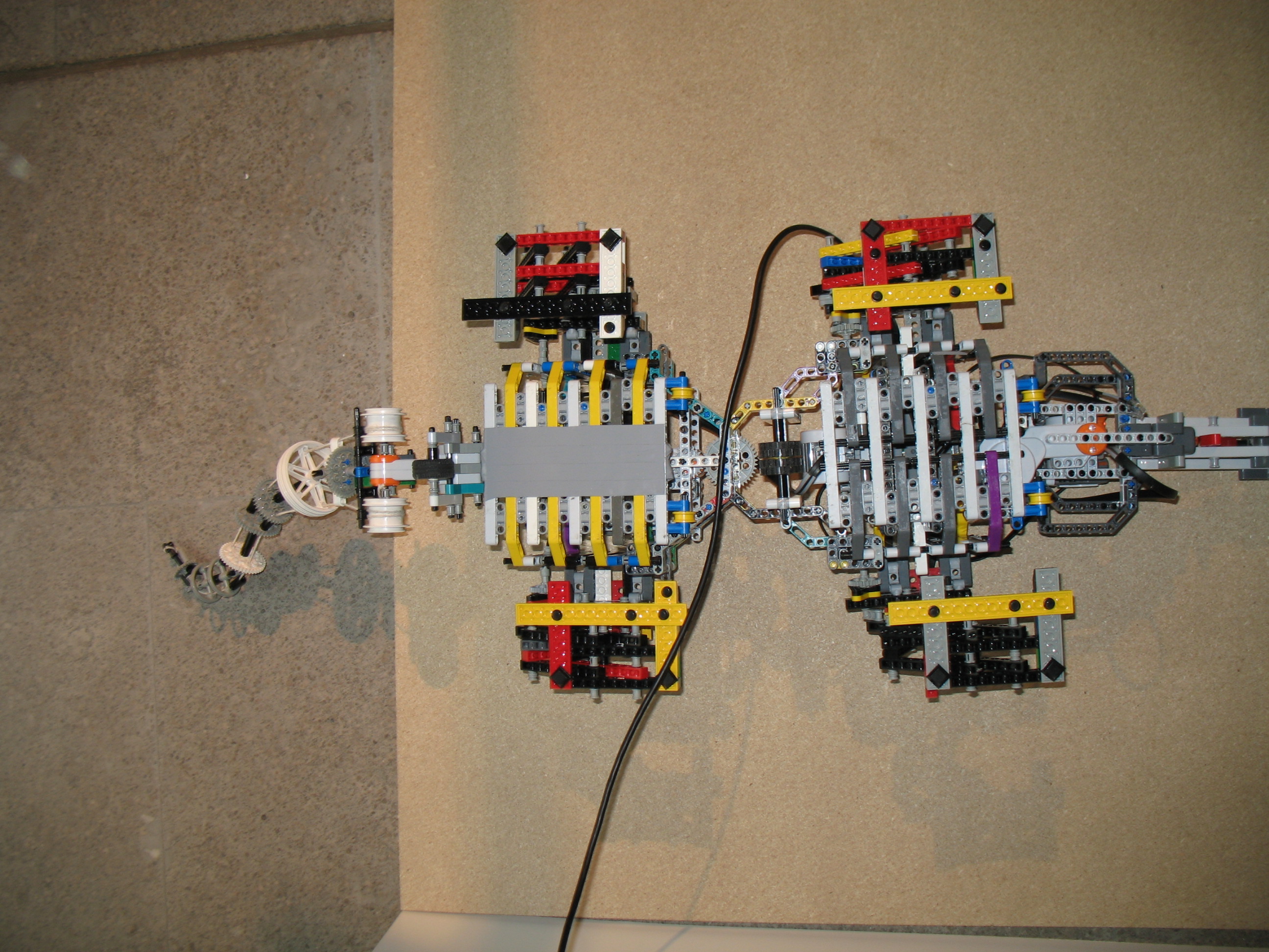
The motor is set to allow the two parts to "flex" a certain amount, which is necessary when walking, and to allow the body to be set either straight, or left or right. To control the amount of flexing, the joint was controlled by a PID regulated motor. The angle between the two body parts is controlled from the reading obtained by the front NXT.
The Tail
The tail was one of the components that came together the easiest, but still has an important aesthetic function. By running a string trough fixed holes in a series of wheels of decreasing size it is possible to create a device that makes a whiplash motion by respectively tightening or relaxing the strings running trough either side of the device. The correct tension was created by running an axle trough a motor and winding the string around it in opposite directions. Thus when one side is tightened the other is relaxed. The end motion is shown below.
I/O and NXTs
The robot is controlled by two NXTs, six motors and three sensors. Compared two the design document, that is fewer sensors than intended, but this was a necessary result of the deadline of the project.
The tail NXT controls the three motors associated with moving and turning the robot. The two set of legs, the front and the tail set, are driven by one motor each. The two motors are driven in sync to optimise the movement of the robot. The third motor is used for controlling the central joint of the robot. The tacho counter of the third motor is used, to ensure the correct rotation is maintained when turning and walking.
The front NXT controls the two motors for the head, and the motor for the tail. Again tacho counters are used, to ensure that the motors keep the right rotation. Additionally the front NXT is responsible reading sensors placed on the head of the robot.
Programming the robot
The robot was programmed using the NXC programming language. Each of the two NXT's is programmed with an individual program, and running several tasks at once, to control the robot. The front NXT is controls the head, and samples the robots sensors, for objects and events to react to. The tail NXT controls the legs and the motor for the central joint.
For communicating between the front and tail NXT, the build-in Bluetooth communication devices are utilised. The two NXT's uses a mailbox-like messaging protocol, were the front NXT sends simple commands, like walk, stop, turn left etc, to the tail NXT.
The primary control over the robot comes from the front NXT, which is the master NXT in the Bluetooth communication. The NXT samples data from primarily the ultra sound sensor. This includes measuring the distance to objects at different head angles, and devising a route based on this information. Commands are subsequently sent to the tail NXT which controls the legs to walk the planned route
The complete source code of both programs, and the utilised libraries, can be found here.
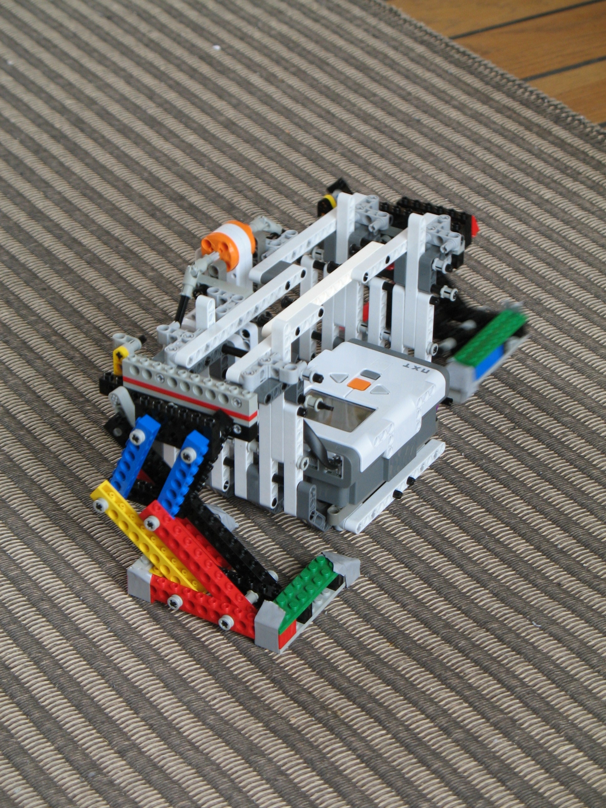
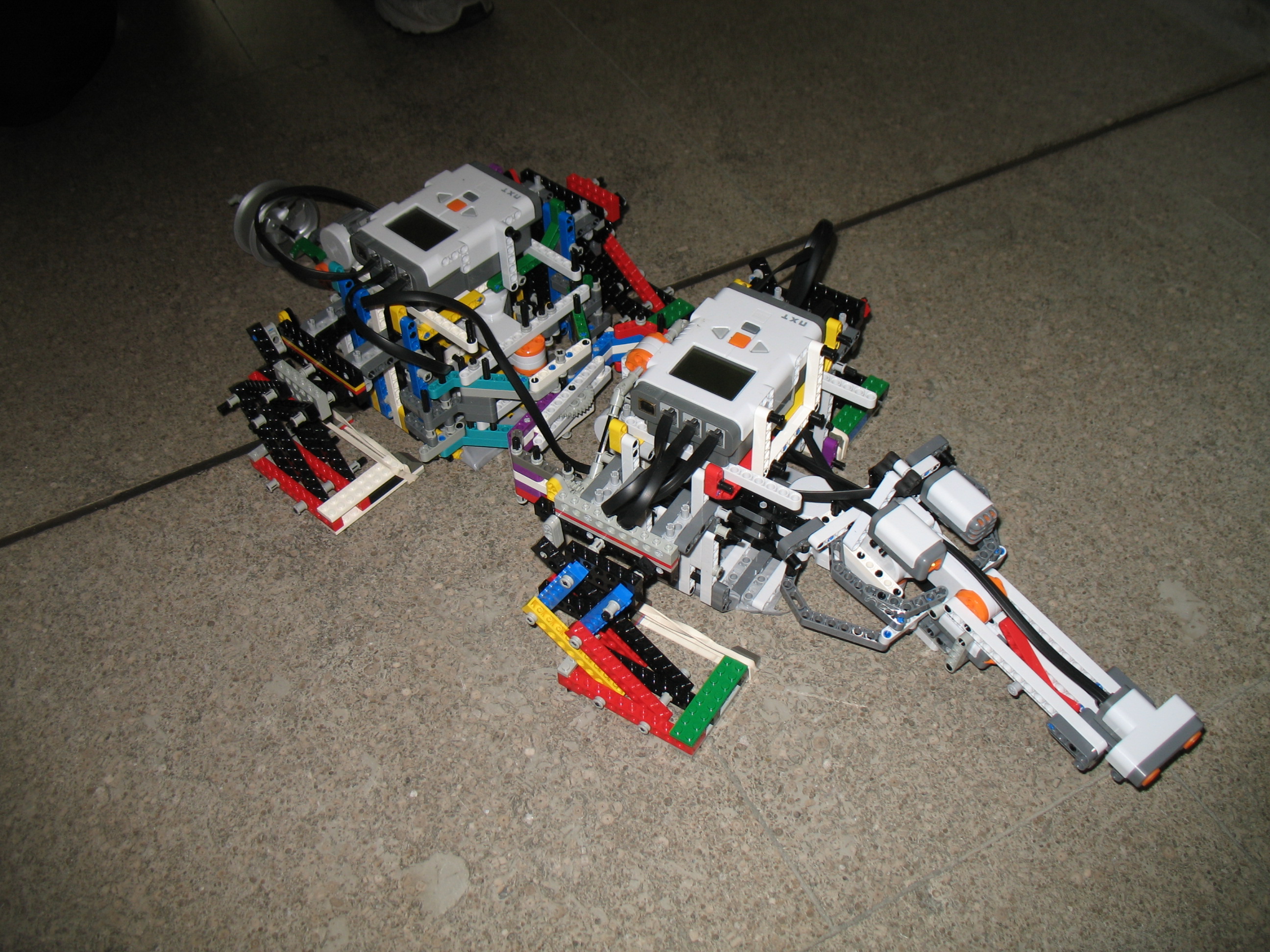
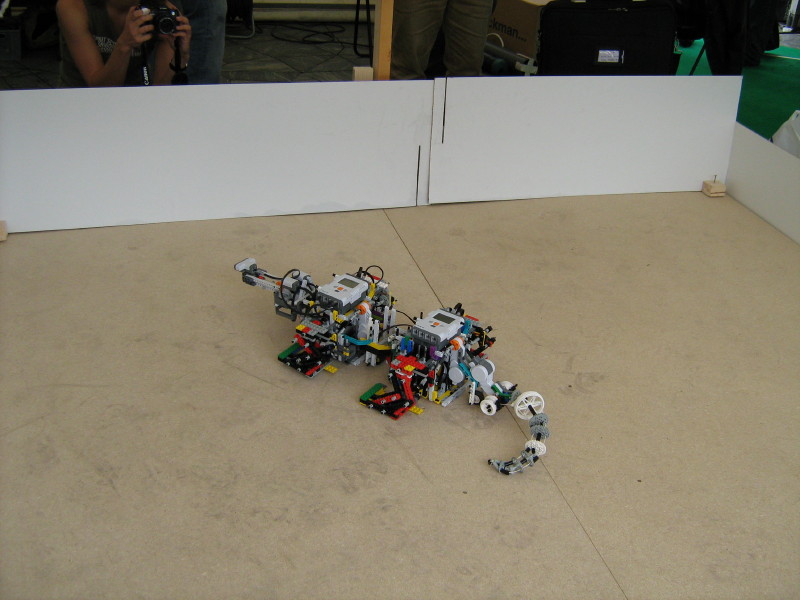
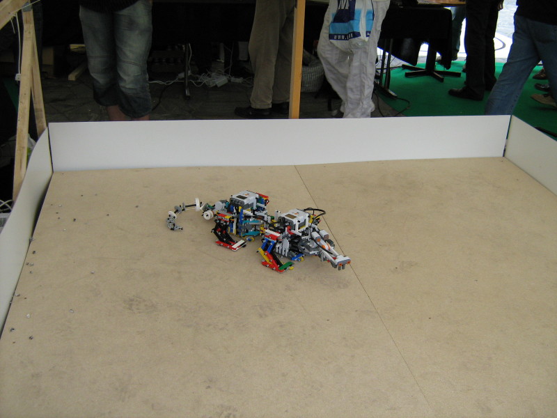
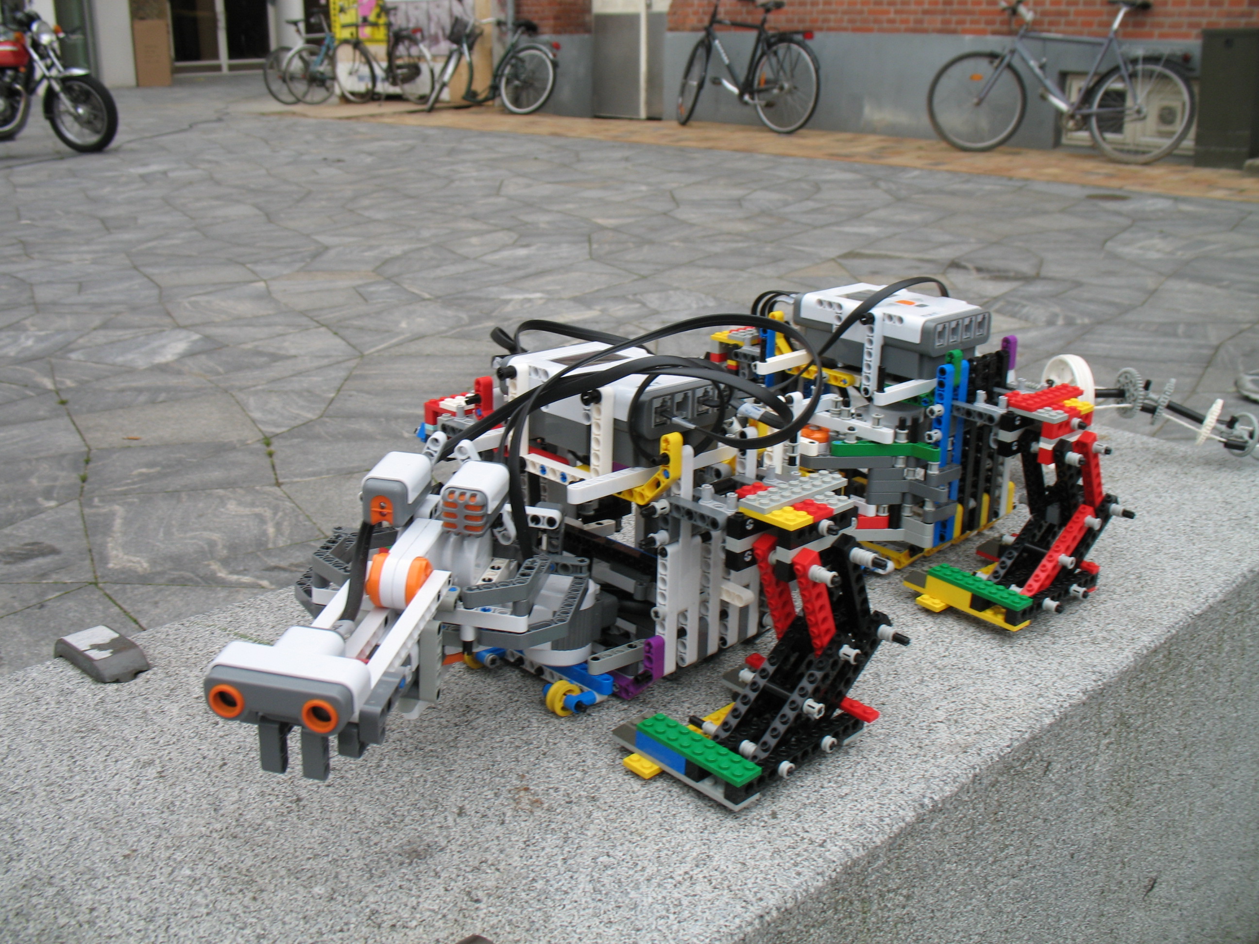
The Robot
The following two videos show the complete robot in action
The following pictures were take at the robots at play festival.
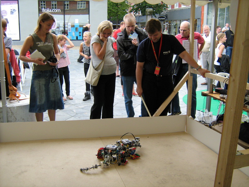
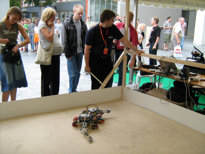
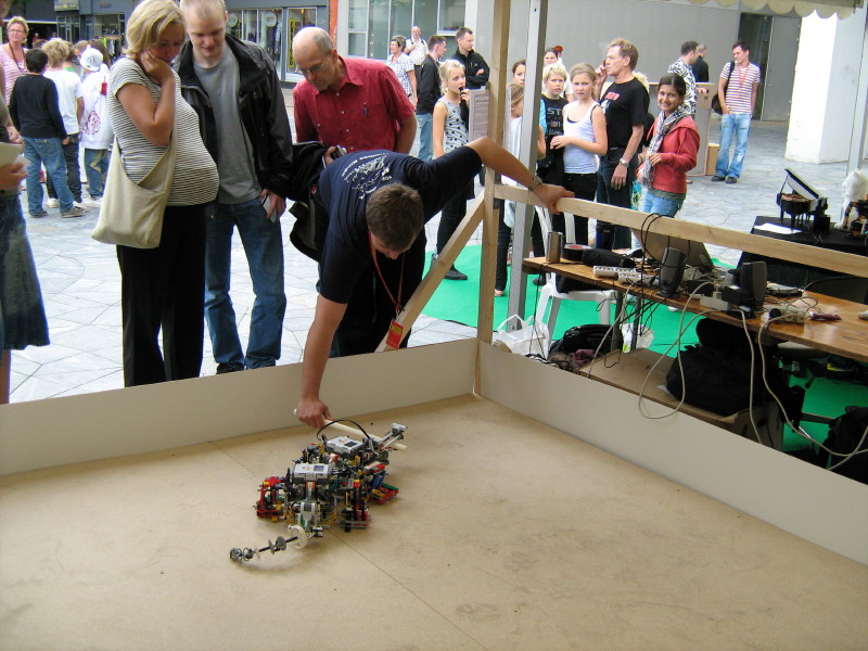
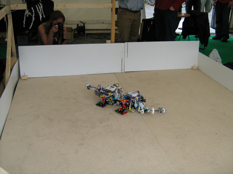
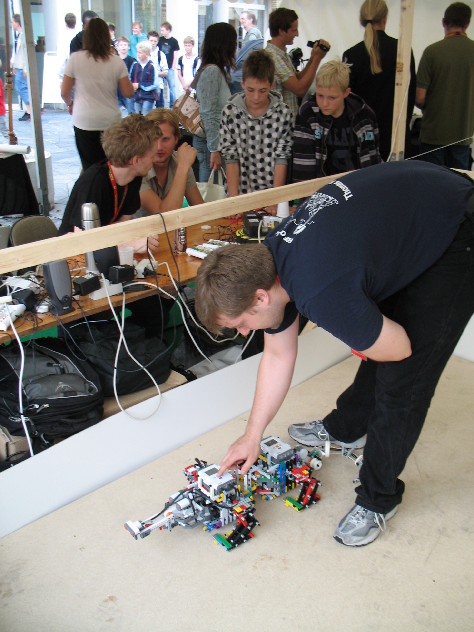
The RobotsAtPlay Festival LEGO Crocodile presentation paper.
Bjørn Grønbæk, Jon Kjaersgaard and Rasmus Svendsen